Virtual Machine
Table of Contents
Abstraction
If one thinks about it, abstraction is nothing but the most efficient form of trade contract. In this contract a seller of a service can announce the services it is offering with every single detail captured in it and interested customers can avail it without having to have a side discussion outside the contract. Similarly a customer can announce the service it needs and any seller that wants to provide it can contact the seller. If this sounds too capitalistic, that is because it is capitalistic, every single thing interaction in the world is about capitalism!.
Abstraction's beauty is in its completeness (neccessary and sufficient). If the contract has been published, no further discussion has to happen between seller and customer (atleast regarding trade terms). What that means is that if the everyone creates their own contracts and people start following some conventions to standardise terms of different kinds of trades, then for that kind of trade any customer can connect with any seller at minimum possible effort. This results in more number of experiments around how to provide service for a certain trade type, which further fuels higher quality services at a much faster rate of availability. This is why we need abstractions.
Abstraction is most highlighted when working with computer systems. Everything is an abstraction over an abstraction over an abstraction and so on. In such systems, one needs to limit the layers of abstraction one dabbles into, as one can't possibly work on or understand every abstraction layer. Carl Sagan famously said that "If you want to make a sandwitch from scratch, you need to first make a universe", so focus on the nitty gritties of what abstraction you have been given and what abstraction you are trying to provide by building on top of it.
Virtual Machine
Do you think computer is a complex machine! It surely is but its core design is so simple that one can intuitively comprehend it and maybe even come up with it with some brainstorming. This is the revelation I had when I looked at the interface and the state of a virtual machine.
As a programmer, I deal with some or all of the following things on a regular basis. Writing a simple VM helped me understand the foundation and reasoning behind each one them -
- Memory allocation and deallocation for storing intermediate results.
- Input Output.
- Debugger
Related post - Digital Machine Layer by Layer
Implementation
Implementation of 16-bit virtual machine (VM). Please note that this implementation is inspired by LC3 but does not completely follow it, infact implements instructions and design using my own intuition. (Checkout code at https://github.com/SaurabhGoyal/vmrs/)
What value and API does a VM provide?
- A virtual machine is a mock for a real machine, in our case a CPU.
- The main value that CPU provides is to run instructions.
- To run the machine, a program code has to be provided which is nothing but an array of instructions.
- The instructions themselves need to be in machine code, each instruction being a 16-bit value.
- The machine will simply execute and step through each instruction of the program one at a time.
- The instruction-set would be of Assembly language as it is smaller and easier to implement.
- The above is sufficient if we do have a machine which can not be interrupted (i.e. given additional input) during its execution. However, to add support of
interruptionof machine, we need a way for machine to be able to take new input, process it and generate a response of the execution of the input.
How does it work internally?
- Machine needs to do following -
- take data
- take instructions
- perform their calculations
- produce results
- listen to external events such as IO devices.
- To take and store the data, instructions and results, a storage layer is needed, this is enabled by
Memorywhich mainly providesreadandwritefunctionalities. - To perform calculations, real hardware uses the logic gates implemented in the electronic circuit and these gates are encapsulated behind a component called
Registers. In our vm -- We would have registers as a storage array and the logic of instructions would be implemented by us manually in the runtime environment (i.e. Rust) itself.
- Data will flow between registers and memory as per need of the instruction.
- For listening to external events, a concept called
Interruptsis implemented.- In real hardware, interrupts are enabled by having dedicated interrupt input pins (electric signal receivers).
- External systems can set the value in these pins as per the interrupt they want to trigger.
- The circuit of CPU is built in a way that in each instruction cycle, if the pin values are off, the normal instruction would be executed and if not, the circuit of interrupt handling branch will get enabled.
- Interrupts can be software triggered as well in which case dedicated registers (special purpose registers) or dedicated memory (memory mapped registers) can be used to track the interrupt status.
- In our project, all of this will be orchestrated by a module called
Simulatorwhich acts as a supervisor of VM and interrupts and the message passing between them. Simulator will also act as an external system for user (us) to be able to interact with the system. - In our VM, we would make the CPU yield control back after each instruction cycle so that pending interrupts can be read and processed.
- A module, called
Interrupt Controller, is added as to take input from user / external systems and pass on to VM. A separate module decouples machine execution and external events making them happen in non-blocking way in relation to each other.
Components
Machine
- Machine has three components -
- Registers - For control purpose. Each register can hold a 16 bit value. There are 10 registers in this implementation -
R0-R7- value storage during instruction executionRPC- program counter, i.e. memory address of the instruction to be executed nextRSTAT- status storage of machine based on various situations such as result sign of previous instructions, blocked on IO, halted etc.
- Memory - For data storage purpose only. This provides a larger storage area than registers and is used purely for storage of data. Each memory slot can hold a 16-bit value. (Read further about Memory-Segmentation section to understand about segment-id and its use in memory-slots.)
- Interrupt Table Address - Stores the address of the table that will hold map of interrupt handler logic for interrupt handling purpose. Read upto Interrupt-Handling section for full details.
- Registers - For control purpose. Each register can hold a 16 bit value. There are 10 registers in this implementation -
- Machine exposes following APIs -
Load()- Takes and stores any data in the memory. Programmer should use it to vm load data and program code into memory at desired addresses. (This is programmer's responsibility that the addresses of the data in the program code point correctly to the loaded data in memory.)SetPC(addr)- Sets the program counter (RPC) of machine to given address. Further execution will continue from this address.Exec()- Executes one cycle of the programm using the instruction stored atRPC.HandleInterrupt(interrupt)- runs the handler code corresponding to the given interrupt. This will be called manually by interrupt controller if needed. (Read upto Interrupt-Handling section for full details.)
- Machine keeps loading the instruction at the memory address referred by
RPCand executing the business logic of that instruction. If the instruction isOP_TRAPwithTRAP_HALT, machine exits the program.
Interrupt Controller
- Interrupt Controller has a single component Pending Interrupt Queue where any incoming and non-handled interrupts are stored.
- We will model each interrupt as a single 16 bit data item.
- Interrupts themselves are simple signal mechanisms of an event happening and do not carry with them the data of the event.
- The data of the event should be put into an area commonly accessible by the external system as well as machine.
- Such area can be VM memory and special registers (such as Memory mapped registers) or dedicated managed-memory (separate from CPU, accessible via MMU - Memory Management Unit).
- In the former case, external system can use vm's
loadAPI and then use interrupt-controller'sintAPI. - It exposes two APIs -
Int(interrupt)- Adds an interrupt to the pending queue. It may discard them as well depending on if they are duplicate or too soon or any other factor. This will be called by the external systems.IntAck(interrupt)- Acknowledges an interrupt handling to be complete and removes it from pending interrupts queue. This will be called based on interrupt handling response from VM.
Exmaple Flow
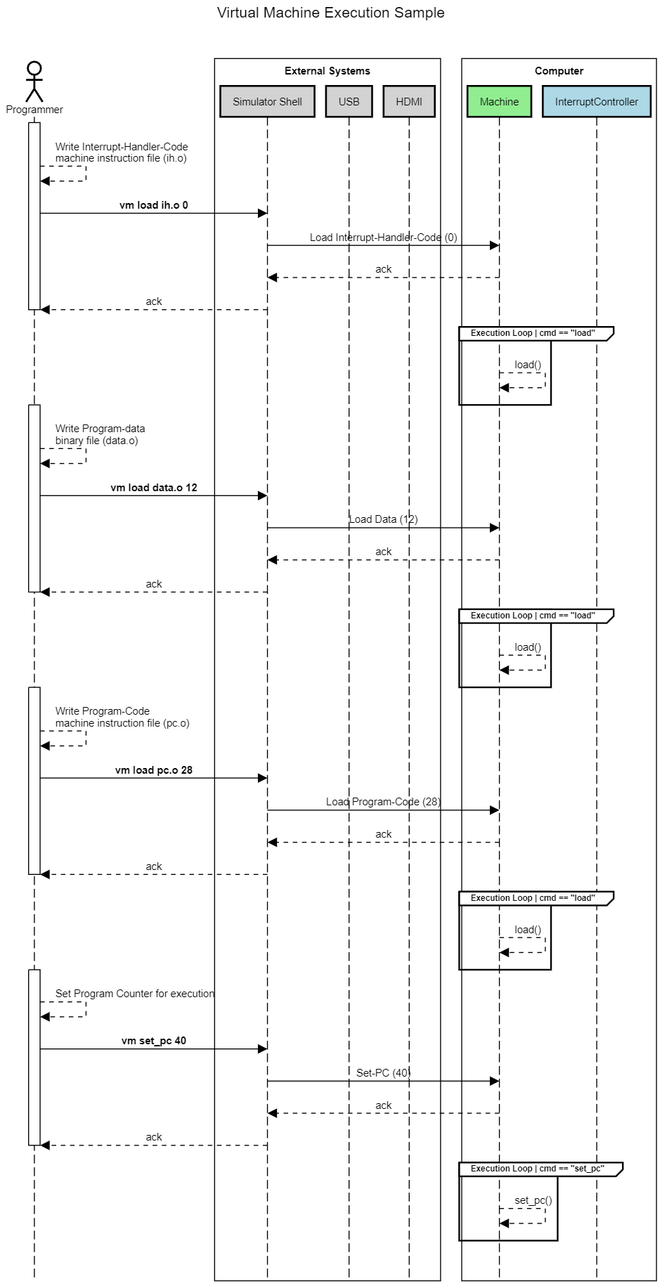
Setting up the machine and the program
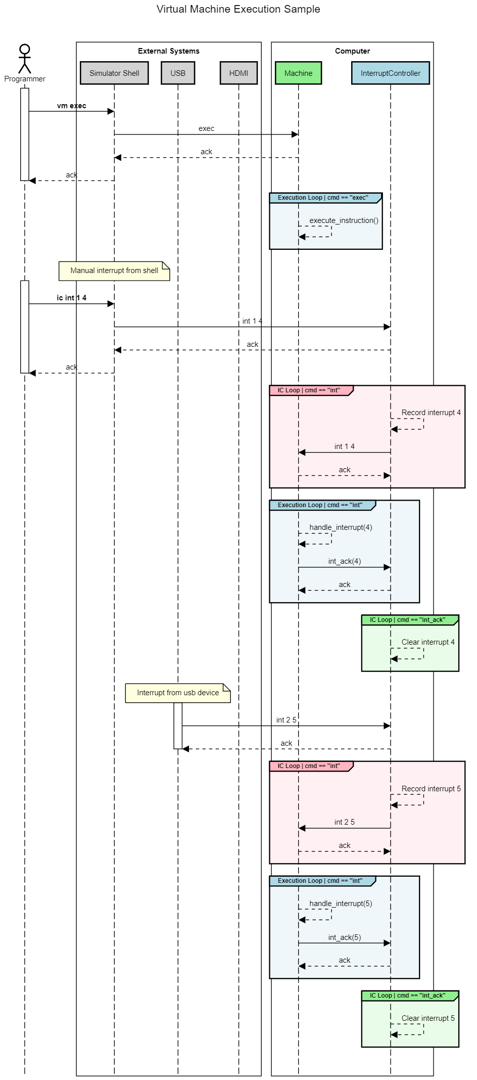
Running the program and handling interrupts
Doubts
- Why to model registers as unsigned ints and then handle the negative numbers manually in VM logic instead of modelling them as signed ints only?
- Because registers in hardware are simple bit storage devices and do NOT care about the data they hold, i.e. they do not have a direct understanding of numbers, let alone positive or negative. This also keeps the hardware API simpler for different users to build whatever logic they want to build on top of a bit array register.
- Ref - https://stackoverflow.com/a/27207704/2555504
- Why do we need Program-Counter reigtser (
RPC)?- To support non-linear execution of code which is powered by
go-to / jumpstatement enabling connstructs such asif-elseandloop.
- To support non-linear execution of code which is powered by
- Why do we need a dedicated register (
RSTAT) for maintaining the sign of the result of previous instruction when the same can be checked from the result itself?RSTATis a dedicated register for a quick lookup of multiple things such as sign of last result (+ve / -ve), status of last operation (underflow / overflow), augmented information of last result (carry) and various interrupts. While the sign can be directly checked from result, the check is mostly conducted in some kind of branching decision context which is where status register provides information in generic sense.- This register has been named as
RCONDin the referring blog post and is also called asCondition Code Registeror simplyCondition Registersometimes.
We are using a dedicated op-code for not treating an instruction as operation, for storing raw data in memory. This wastes 4 bits, is there any workaround?Using the two step (load, run) process now instead of the single step (run-with-load), resolving this issue.
- Why is an address needed to vm load the program code? While I haven't used any custom address, i.e. loaded the program code simply at 0th address, the blog post suggest to use 0x3000, why?
- The reason is simply that in real world, machine may have more things that it needs to manage in the memory other than just the program code to be executed. One such thing is trap routine code which is nothing but some special instructions that machine itself has hardcoded to provide functionalities such as talking to IO devices and halt the program.
In-Depth
Memory Access Control via Segmentation
While primary use of memory for machine is simple storage, we do need some additional semantics for the proper functioning of the machine. In any bare minimum vm, there are atleast three types of information that a memory slot can store -
- Program data - static data that a program will use such as numbers and strings.
- Program code - the instruction that a program is made of.
- Generated data - the data generated during the program execution and at the end of it. Ex.- temporary values during execution and permanent values as result.
A program must not able to overwrite its own instructions during execution or overwrite the program-data as it would cause errors when accessing that memory slot. So we need to put some kind of access control on slots. A simple technique for the same is memory segmentation where each memory slot has data as well as a segment_id to represent the category of the data it holds. Using this segment_id, following logic can be applied for access control -
- A write on a slot can succeed only if the slot's current segment is either uninitialised or is same as the segment of the data being written.
- A write on a slot can be restricted to certain segment_types depending on who is calling.
- A read on a slot would return segment of data as well so the caller can use that to assert that they are treating the data with the same expectation that it was written with.
In total we have following segment types -
- Uninitialised (0) - Memory slot is still up for grab.
- Interrupt-Data (1) - Memory slot is reserved for storing data uploaded by external systes to augment interrupt signals.
- Interrupt-Handler-Table (2) - Memory slot is reserved for storing the mapping between interrupt-code and the absolute memory address of its handler logic.
- Interrupt-Program-Code (3) - Memory slot is reserved for storing the instructions for handler logic.
- Program-Data (4) - Memory slot is reserved for storing the hard-coded data loaded by programmer.
- Program-Code (5) - Memory slot is reserved for storing the instructions loaded by programmer.
- Dynamic-Data (6) - Memory slot is reserved for storing the data dynamically generated during execution of instructions.
Out of all above, all segment types other than Dynamic-Data are privileged segments and can be written to only via Load API. This is essentially a reflection of what we call kernel mode.
Read the Interrupt Handling section for more details on need of all these segments.
Interrupt Handling
We saw in the interrupt handling flow how an interrupt is triggered by an external device and how CPU handler handles it and sends an ACK back. Few details are still missing though -
-
How does machine know how to handle a certain interrupt? To enable this, machine provides following two types of memory segments as we saw in Memory-Segmentation section.
- Interrupt-Program-Code (3) - The handler logic of each interrupt_id can be stored in memory slots with this segment-id.
- Interrupt-Handler-Table (2) - The mapping of interrupt_id to the absolute memory address of the handler logic of interrupt_ids can be stored in memory slots with this segment-id.
-
How does the external device shares the data related to the interrupt with the machine? For ex.- the input character in case of a keyboard char-input interrupt? To enable this, machine provides following type of memory segments as we saw in Memory-Segmentation section.
- Interrupt-Data (1) - Any data needed for the interrupt can be stored in memory slots with this segment-id. This will be loaded by external systems.
-
How does machine know when to stop and when to continue? To enable this, machine uses the value in
RSTATregister which marks whether execution should execute instructions or wait for some external event. Value inRSTATcan be set by specificTRAPinstructions. Ex.-- If a program needs user input, it adds an instruction in the program
TRAP_GETC. - Machine sets
RSTATasRSTAT_WAITING_FOR_INPUTas per this instruction and DOES NOT increase the program counter because we want to wait for this to complete. - In further execution cycles, machine does not perform any instruction because of
RSTATvalue. Another such value which stops machine to perform anything isRSTAT_HALT. - In the interrupt handler code of machine, machine should check whether it wants to handle the
INTERRUPT_GET_Cbased on value ofRSTAT. - If yes, current program-counter is stored temporarily,
RSTATis reset toRSTAT_CONDITION_ZEROand interrupt handler logic from memory is executed. Post execution, program-counter is increased by 1 from the persisted program-counter so that execution continues back from the user-program.
- If a program needs user input, it adds an instruction in the program
Flow Diagram
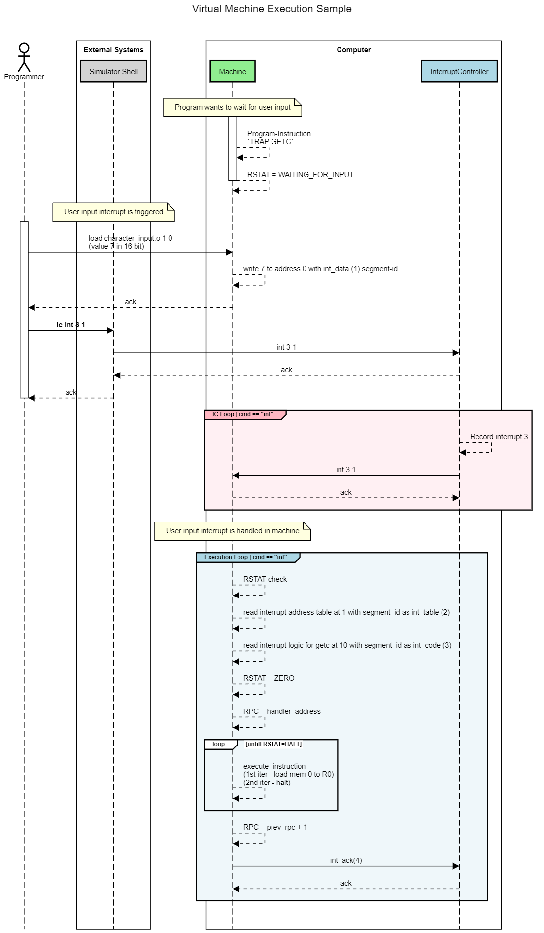
Example Run
In this example, we are taking a number as input from user and doubling it by adding it to itself. The logic would go like this -
-
Load the needed static data into machine memory -
-
We need memory slots for external devices to write to. We assign addresses 0-7 for that.
-
We need memory slots for interrupt-address-table. Table currently has only one key value entry, interrupt_id 1 has handler logic at 10. We assign addresses 8-9 for that.
vm load src/sample_programs/int_handler_address_table.o 2 8 -
We need memory slots for interrupt-handler-logic for getc (
src/sample_programs/int_handler_getc.o). The logic has only two instructions - load from 0 to R0 and halt. We assign addresses 10-11 for that.vm load src/sample_programs/int_handler_getc.o 3 10 -
We need memory slots for program-code for getc demo program (
src/sample_programs/getc.o). The logic has three instructions - Trap Getc, add R0 to R0 and halt. We assign addresses 12-14 for that.vm load src/sample_programs/getc.o 4 12
-
-
Once loaded, we set the program counter to the address of the program.
vm set_pc 12 -
To start execution of demo program. We use
vm exec. The program will execute first instruction (TRAP_GETC) and halt because of waiting for input. -
To trigger user input interrupt -
-
We load value 7 into the int_data segment memory.
vm load src/sample_programs/character_input.o 1 0 -
We trigger the getc interrupt (1) from device_id 3.
ic int 3 1
-
RUST_BACKTRACE=1 cargo run -q
vm load src/sample_programs/int_handler_address_table.o 2 8
vm load src/sample_programs/int_handler_getc.o 3 10
vm load src/sample_programs/getc.o 4 12
vm set_pc 12
vm exec
vm exec
vm exec
vm load src/sample_programs/character_input.o 1 0
ic int 3 1
vm exec
vm exec
Instruction-Set
General syntax
OP_CODE - (4 bits) | OPERANDS (12 bits)
Commands
Data (OpCode - 1110)
- Stores given value in memory.
- Syntax -
1110 (4 bits) | Data (12 bits)
ADD (OpCode - 0001)
- Adds two values and puts the result into a destination register. The values van be either fetched from registers or given in-place.
- Syntax -
0001 (4 bits) | Dest Register (3 bits) | Source-Register-1 (3 bits) | Mode (1 bit) | Mode-Specific-Operands (5 bits) - Two modes
- Register mode (Mode bit 0) - When second operand data is in another source register.
- Syntax -
0001 (4 bits) | Dest Register (3 bits) | Source-Register-1 (3 bits) | 0 (1 bit) | 00 (2 bits) | Source-Register-2 (3 bits) - Immediate mode (Mode bit 1) - When second operand data is in the instruction itself.
- Syntax -
0001 (4 bits) | Dest Register (3 bits) | Source-Register-1 (3 bits) | 1 (1 bit) | Sign-of-Value (1 bit) | Number-of-Value (4 bits)
Load (OpCode - 0010)
- Loads the value given in the instruction to the destination register for later use.
- Syntax -
0010 (4 bits) | Dest Register (3 bits) | 0 (1 bit) | Sign-of-Value (1 bit) | Number-of-Value (7 bits)
LoadIndirect (OpCode - 0011)
- Loads the value at the memory address given in the instruction to the destination register for later use.
- Important thing to note is that the address will be relative to the program code instructions and not absolute. This means that the relative address can be negative and should be sign-extended.
- Syntax -
0011 (4 bits) | Dest Register (3 bits) | Relative-Memory-Address (9 bits)
LoadRegister (OpCode - 0110)
- Loads the value stored in the source register given in the instruction to the destination register for later use.
- Syntax -
0001 (4 bits) | Dest Register (3 bits) | Source-Register (3 bits) | 000000 (6 bits)
Jump (OpCode - 0100)
- Sets program counter to the memory address given in the instruction.
- Enables non-liner execution of program.
- Syntax -
0100 (4 bits) | 000 (3 bits) | Relative-Memory-Address (9 bits)
JumpIfSign (OpCode - 0101)
- Sets program counter to the memory address given in the instruction if the register given in instruction has negative value.
- Enables non-liner execution of program.
- Syntax -
0101 (4 bits) | Dest Register (3 bits) | Relative-Memory-Address (9 bits)
Trap (OpCode - 1111)
-
Sets a trap to the instruction execution for machine to do things outside the instruction in the program code.
-
These things can be things such as talking to IO decices or halting the program. Simple way to imagine is that this is a set of machine defined functionalities to interact with outside the program-code and machine scope.
-
Since these things are something that machine implements on its own and are not part of user-defined instructions, machine implements them itself and stores the implementation logic in memory. This is the reason, machine may need some part of its memory for its own things and program code would be stored at a non-zero address, typically 0x3000.
-
NOTE - This memory address is needed mostly for the real hardware where the instructions for handling a trap code are written in machine code (translated from assembly) and stored in the memory. For our case (VM), we would implement them in the Rust runtime only so no dedicated memory address is needed.
-
Because of multiple types of traps and their distinct nature of being a foreign-function-interface instruction, they have been categorised into one opcode where the trap type can be passed as an operand, instead of creating a dedicated opcode for each trap. https://www.jmeiners.com/lc3-vm/#trap-routines
Trap for additional functionalities You may be wondering why the trap codes are not included in the instructions. This is because they do not actually introduce any new functionality to the LC-3, they just provide a convenient way to perform a task (similar to OS system calls). In the official LC-3 simulator, trap routines are written in assembly. When a trap code is called, the PC is moved to that code’s address. The CPU executes the procedure’s instructions, and when it is complete, the PC is reset to the location following the initial call.
Note: This is why programs start at address 0x3000 instead of 0x0. The lower addresses are left empty to leave space for the trap routine code.
-
Syntax -
1111 (4 bits) | 0000 (4 bits) | TrapCode (8 bits) -
Trap always works with R0 only, i.e. if it reads character, it would store in R0, if it prints character, it would load value from R0.
-
Trap codes -
- Halt (0) - Stops the program execution.
- GetC (1) - Blocks the program to get one character from keyboard and sets it it R0.
References
- https://en.wikipedia.org/wiki/Little_Computer_3
- https://en.wikipedia.org/wiki/Little_man_computer
- https://www.jmeiners.com/lc3-vm/#:lc3.c_2
- https://en.wikipedia.org/wiki/Interrupt
- https://www.youtube.com/watch?v=oArXOAhzOdY&list=PLUkZG7_4JtUL22HycWYR_J-1xJo7rQGhr
- https://www.andreinc.net/2021/12/01/writing-a-simple-vm-in-less-than-125-lines-of-c